Following the introduction of NEx64T in the previous article, it is now time to start bringing some facts to back up the claims presented there.
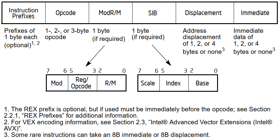
x86 and x64 are well known to be particularly problematic when it comes to decoding their instructions, due to the design choices that have been made over the years, as we have already seen in the diagram previously reported, which I reproduce for convenience:
On the other hand, NEx64T was presented as much simpler in that it does not make use of any prefixes and has a more ordered opcodes structure that is much easier to decode, which is the result of completely different design choices (on the other hand, and as already mentioned in the other article, with hindsight it is easy, though by no means obvious, to do better).
Instruction formats
To facilitate this, I have included a few slides to better clarify the format of the opcodes, why certain choices were made, and some statistics (which are also useful in understanding why decoding is far easier than with x86/x64):
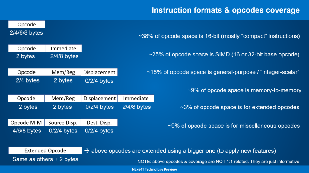
On the surface, it might seem more complicated than x86/x64, because we have as many as five formats for opcodes plus an extended version of them (using a larger opcode), whereas Intel’s diagram would apparently show only one format.
In reality, Intel’s diagram simplifies a situation that is quite different, as it also encompasses the first four formats of NEx64T, as well as the opcode extension (which is equivalent to the use of prefixes on x86/x64). The only new format is the fifth, because it allows two operands to be specified in memory, which wasn’t seen before.
The information to the right of the slide is not directly related to instruction formats, but is purely statistical and provides data on how these formats are distributed within the opcode space. They are, therefore, only useful for understanding how this space is used; geeks material, in short.
The problems of decoding
In any case, and going back to the two abstract diagrams (the one from Intel and the one above from NEx64T), these do not provide any concrete idea of the complexity of decoding instructions, as they lack concrete details or, in general, useful information for the purpose.
In particular, we need to understand how to retrieve:
- the length of the instruction;
- the length of the basic opcode (i.e. net of any immediate values and/or operands in memory);
- whether the instruction has an immediate value or not and, if so, how large;
- whether the instruction has an operand (or even two, for NEx64T) in memory or not;
- whether the operand(s) in memory, if any, has an offset and, if so, how big it is (or they are);
- the position (within the bytes of the instruction) of all the above elements (base opcode, immediate value and offset).
This is the bare minimum the instruction decoder needs to understand at least what it is dealing with and what information it will need to extract (where and how much, in particular) in order to be able to get on with the rest of the work.
At the moment it is not even important to know what type of instruction it is (integer/scalar, FPU, SIMD, …) or the specific instruction, because this will only be needed in the next steps (the following stages of the pipeline).
Decoding for x86/x64: prefixes!
As you can imagine, deriving the above for x86/x64 is quite problematic, due to the structure of its opcodes, which is anything but trivial (just review the diagram at the beginning).
The first thing the decoder has to do is to hunt for prefixes. Instructions can be a maximum of 15 bytes long, but they can also contain an unspecified number of prefixes (of course, there must then be the opcode and its arguments, if any).
This requires scanning the first few bytes by marking whether a byte turns out to be a prefix or not. At this point, tracing the opcode becomes easier: just find the first byte that has not been recognised as a prefix.
Attention must, however, be paid to certain special cases:
- prefix
0Fintroduces a new opcode map (up to 256 new instructions). So the decoder will have to take the next byte, but maybe add something to it (e.g. 256. Which in hexadecimal isox100) to get the actual value to be used to distinguish these new instructions from the normal/basic ISA instructions. Basically, the normal opcodes will go from 0 to 255, while the new ones introduced by0Fwill go from 256 to 511; - two opcodes within
0F,0F 38and0F 3A, further expand the opcodes with two maps of 256 instructions each. So if the decoder has found the0Fprefix (as per the previous point) it still has to do an additional check after picking up the next byte, see if this is38or3A, and in this case go and pick up the next byte which will be the actual opcode. Again, this will take care of adding an appropriate value (e.g. 512 =0x200and 768 =0x300) so as not to confuse these new opcodes with the previous ones. In the end, with these two mechanisms, you can have up to 1024 instructions in total; - similarly to
0F, Intel has introduced additional 2- or 3-byte prefixes with the AVX extension, which adds a simpler, more versatile and more compact mechanism for SIMD (SSE) instructions, as well as some new integer/scalar instructions. Again, the decoder must first check that it is faced with a two-byte prefix (C5) or three-byte prefix (C4), and then extract the next byte or two bytes and store their values somewhere (internally), which it can use to expand the opcode map, but in general to introduce new registers and new functionalities (SIMD registers twice the size of SSE, for example); - since it needed to further extend the SIMD unit, Intel then added a further prefix (
62), this time of no less than 4 bytes, with the AVX-512 extension so that it could specify further new registers and several other functionalities. Again, as with AVX, the decoder will have to extract all the information from the three bytes following this prefix, and store it internally; - AMD had also got busy in the meantime and introduced a new prefix (called REX) that makes use of 16 contiguous opcodes (
40to4F) in the new 64-bit mode (x64. Initially calledx86-64and later alsoAMD64orEM64TorIntel 64). In this case, the decoder, after verifying that it is one of these 16 prefixes, takes care of extracting the 4 bits it carries and stores them internally to select new registers or force the size of the data to be manipulated for the instruction (e.g. use 64 bits instead of 32); - finally, Intel has further complicated things with the brand new APX extension (which we talked about in a recent series of articles), which has introduced a further two-byte prefix (
D5) called REX2 and which, as the name suggests, works in a similar way to REX, but carries a lot more information (8 bits instead of 4). So here too, the decoder will have to extract the information of the next byte and store it internally.
These prefixes are the most complicated to handle, while all the others are simpler because they are concerned with changing the behaviour of the instruction with regard to a single characteristic:
F0, also calledLOCK, indicates that the processor must perform an atomic read-modify-write operation. The problem here is that the use of this prefix is only allowed with a few instructions, so the decoder will have to check that the instruction it is decoding is one of them, and if not, raise an exception (of illegal instruction);F2andF3are used for repeating so-called string operations (these are a few instructions:LODS,STOS,MOVS,INS,OUTS,CMPSandSCAS). In this case, the decoder will have to check the type of instruction, the prefix used (which has a different meaning for some of these string instructions), and report this to the backend (which is in charge of the actual execution of the instruction), so that it knows how to handle them. As if this were not enough, these two prefixes were used by the SSE extension to introduce new SIMD instructions, so the decoder will have to take them into account, even in the case of instructions using the prefixes0F,0F 38and0F 3A;26,2E,36,3E,64,65are used to force the segment/selector to be used for the source operand in memory, instead of the default.3Eand2Eare also used in jump instructions to signal that the jump may or may not be taken, respectively;66changes the size of the data to be manipulated. It therefore indicates to use 32 bits instead of 64 bits, for example, or 16 bits instead of 32;67changes the size of addresses. So it will truncate 64-bit addresses by making them 32-bit, or 32-bit addresses by making them 16-bit.
I think it is evident how much work is required and how many complications arise for the decoder in order to extract the information that qualifies the particular instruction and, finally, to obtain what is actually the operation to be followed (what I called the basic opcode, above).
Although I must add that there are several other special cases that make use of prefixes to implement further extensions (MPX, SGX, TSX, …), and which I preferred not to mention so as not to make the article even heavier. So be aware that the real situation is even more complex!
Decoding for x86/x64: operand in memory and immediate value
But this is certainly not the end of the story. In fact, what has been described so far only deals with the first part of an instruction, which involves ‘only’ the prefixes and the opcode: the i ModR/M, SIB, Displacement and Immediate fields are still missing (as per the diagram above), because they are optional.
In order to understand whether they are present or not, it is first necessary to obtain the basic opcode, and then to unravel the previous skein. It is, in fact, only now that the decoder is able to understand whether an instruction has an operand in memory and/or an immediate value.
In reality, the thing is not so simple because, as already mentioned in the previous article, the instructions of x86/x64 are not grouped together regularly, but only some are, while others are scattered quite arbitrarily in the four opcode maps we have already seen.
Probably and for simplicity of implementation, the decoder will have an internal map of 1024 bits (one bit for each instruction) which it will consult in order to understand whether or not that particular instruction refers to an operand in memory and, therefore, that possibly immediately after the opcode the byte with the ModR/M field will be present.
If this is the case, it will then have to examine this field because there are certain precise values indicating the presence or absence of SIB, which, if present, will have to be extracted from the next byte. Therefore, checking for the presence of this field is subject to checking the previous ModR/M.
Similarly, by examining a few bits of ModR/M, it is possible to know whether immediately after it, or after SIB, the offset (Displacement) to be used to reference the memory location will be present, and if so, its size (one or two bytes for the old 16-bit execution modes. One or four bytes for the new 32- or 64-bit ones).
In this case, the control of Displacement is subordinate to that of SIB, since, although it is only ModR/M that determines whether it is present or not, it is not possible to know beforehand where to pick up the bytes constituting the offset value.
To close the issue concerning the operand in memory, we must add that the decoding of ModR/M and SIB is a little more complicated, as there are special cases to consider. In fact, sometimes it is not possible to use a particular register in some addressing mode, because this is either to indicate the presence of the SIB byte, in fact, or to indicate the deletion of the base register in the scaled index addressing mode (so there would only be the scaled index and any offset).
Furthermore, in 64-bit mode, absolute addressing in memory (which is only relegated to a couple of specific MOV instructions) disappears, to make way for the new RIP register mode (which, therefore, allows completely relocatable code to be written).
Finally and by similarity, the decoder will probably use an additional 1024-bit map to determine whether that particular instruction has an immediate value or not. It would be possible to carry out this check in parallel with that of the presence of ModR/M, but one would in any case have to wait for the decoding of the latter to be completed (since it is not that simple).
In fact, an immediate value, if present, is always at the end of the instruction, so knowing from which byte to read it is in any case subject to the completion of the calculations relating to the possible operand in memory.
But to complicate matters, it must be said that immediate values present different cases, depending on the particular instruction. Indeed, an immediate value may be:
- of the same size as the data manipulated by the instruction (8, 16, 32 bits);
- 32-bit for instructions manipulating 64 bits (because it is not possible to have 64-bit immediate values). In this case, the 32-bit value will be extended to 64 bits;
- 64-bit, but only with the one instruction that allows a value to be loaded into the accumulator (the
RAXregister); - 8-bit, but extended to the size of the data manipulated by the instruction.
Obviously, the decoder will need to know which of these cases it is in. Apart from the third, which is very simple (there is only one instruction to check), and the second (it is enough to force the reading of 32 bits when the data size is 64 bits), to distinguish between the first and the fourth it could use another bitmap to work out which one it is in.
At this point, the decoder finally has all the elements and information relating to the instruction, which it can pack up more easily and send to the backend for actual execution.
In particular, it is now perfectly able to determine the length of the instruction. I would particularly like to emphasise this point, as it is absolutely fundamental for practically all modern processors, which are capable of executing multiple instructions per clock cycle.
But being able to execute multiple instructions means that the decoder must know the length of the first instruction before it can finally move on to do the calculations to determine that of the second, and so on for the third, fourth, etc.
Since, and as we have seen, already a single x86/x64 instruction requires a myriad of calculations and considerations to be made just to determine its length, one can imagine how difficult and how many resources are required when dealing with multiple instructions to decode and execute per clock cycle.
Decoding for NEx64T
Needless to say, with NEx64T the situation is not only better, but diametrically opposed to the other two architectures. In fact, and although it too has long instructions (potentially even much longer), it is not at all necessary to scroll through the bytes to hunt for all the information we need: it is sufficient to examine only the first bits to be able to extract almost everything we need.
More precisely, the analysis of the first byte (i.e. the first 8 bits) is already sufficient to be able to decode all the fields (with the exception of the basic opcode. But I’ll talk more about that later) of about 89% of the opcode space (not to be confused with the number of instructions).
While reading the next byte, and specifically its six least-significant bits (the architecture is little-endian and the opcode structure is developed from the least-significant bits), allows it to be completed, covering the entire opcode space.
The following slide shows the situation precisely (apart from the approximation of percentages):
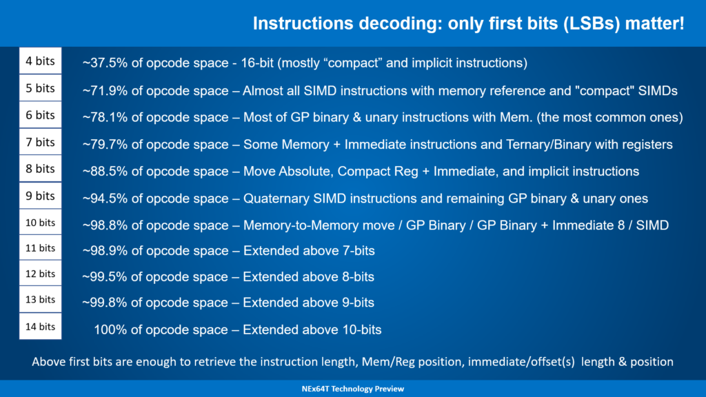
This summary table should be read in a certain way, so it deserves a more in-depth explanation.
Taking the first case, for example, it means that the first four bits (the least significant ones, as already mentioned) of the opcode are sufficient to determine:
- the length of the instruction;
- the size of the base opcode (which, in general, occupies between 2 and 8 bytes);
- whether or not it references an operand in memory;
- if it has an operand in memory, where the
Mem/Regfield is located (the equivalent ofModR/MandSIB, put together. It occupies two bytes / 16 bits); - if it has an operand in memory, indicates whether an offset is present;
- if it has an offset, where it is;
- if it has an offset, how long it is;
- if it has an immediate value, where it is;
- if it has an immediate value, how long it is.
Basically, by examining the first four bits, it is already possible to know all this information immediately, without any additional calculation, for 37.5% of opcodes. In some cases (a few. On the other hand, it is only four bits!) it is also possible to know the opcode of the instruction (e.g. whether it is a conditional jump).
The following write-up attempts to provide some additional information on which opcodes/instructions are covered by this case, specifying that these are 16-bit opcodes, almost entirely dedicated to what are called “compact” instructions (i.e. exact equivalents of other instructions, but taking up less space).
Switching to the second case, i.e. being able to pick up the first five bits, it will be possible to obtain all the above information even (because obviously the instructions of the first case are also added) of the vast majority of SIMD instructions, but this time covering almost 72% of all opcodes!
What is also new now is that most SIMD instructions reference a memory location, so the Mem/Reg field will be present, and hence the offset, if any. But five bits are enough to get all this information (apart from the basic opcode of the SIMD instructions).
And so on: by increasing the number of available bits, it is possible to decode more and more opcodes/instructions and take all the information (sometimes even including the basic opcode). All up to a maximum of 14 bits, of course (100% coverage is achieved).
Speaking also of the aforementioned Mem/Reg, it must be added that the format of this field is quite simple: the addressing modes made available are listed linearly, with their sub-fields in the case where there are several elements contributing to the definition of the specific mode (e.g. the base and index registers for the indexed and scaled mode), and there are no exceptions (as happens, on the other hand, with ModR/M and SIB).
I think that, at this point, the comparison with x86/x64 is merciless, to say the least…
The format of NEx64T instructions
However, not all that glitters is gold. In fact, and as has already been reported several times, the base opcode (of which only the size is known, as reported above) is often missing, which serves to precisely qualify the instruction to be executed, with any registers to be used, the size of the data to be manipulated, particular instruction behaviours, any built-in immediate values, etc.
To do this, it is necessary to analyse the base opcode to extract this missing information, but the task is not as arduous as for x86/x64, since the instructions are not scattered pseudo-randomly in the opcode space, but are grouped in particular structures (called instruction formats, in jargon).
Here are some examples:
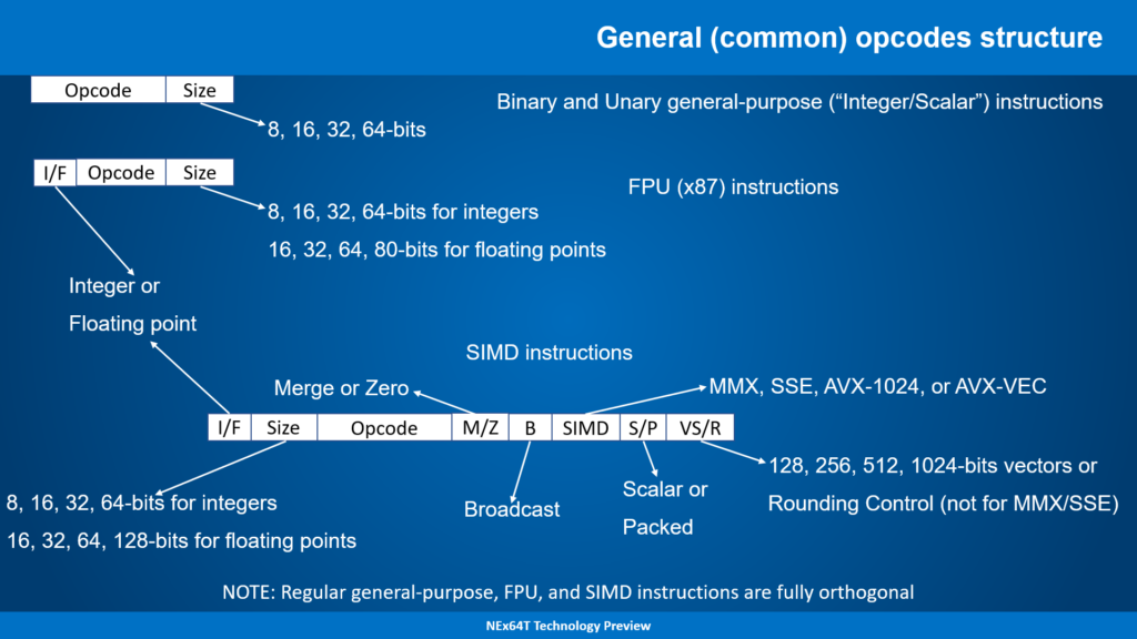
Specifically, the Opcode field contains the numeric code associated with a particular instruction. For example 01000100 (in binary) identifies the SHLD Mem,Reg instruction in the group of binary instructions (those that need two source arguments to perform calculations), while 01001001 corresponds to JMP Mem in unary instructions (with only one argument needed), 11110101 corresponds to FISUBR Mem in the FPU’s unary instructions whose only argument (in memory or in another register) is an integer value, and finally 010000 is the code for the SIMD/vector instruction BLEND V1,V2,V3/Mem,Imm8 (which requires three source arguments).
Interestingly, Opcode only specifies the base instruction, while the data size is in a separate field (Size, which is the only one present in general-purpose instructions. To which is added I/F in those of the FPU or SIMD/vector unit, which is used to specify whether it is an integer or floating-point value).
In this way, there are not so many formats for instructions, because they are structured in a simple and, above all, orthogonal manner. This has also made it possible to considerably reduce the number of instructions.
For example, the above BLEND instruction maps all of the following x86/x64 instructions: VBLENDPD, VBLENDPS, VPBLENDW, VPBLENDD, BLENDPD, BLENDPS, PBLENDW. This is because the size of the data, the type of data (integer or floating point), whether it is scalar or “packed” data (with multiple values), the size of the vector registers, and finally also the type of SIMD or vector extension to be used (from MMX up to AVX-1024, or AVX-Vec which is the new fully vector extension) are all parameters of the base instruction (of any base instruction, to be precise, due to their orthogonality).
It must be said that compared to many Load/Store (L/S: the former RISCs) architectures, I used more formats for the instructions, which made better use of the space available for opcodes (which is always limited, even for a variable-length architecture), but not in an exaggerated and therefore perfectly manageable manner.
In particular, a large part of the formats relate to so-called ‘compressed’ instructions, which are duplicates of normal instructions, but take up less space. Obviously, the aim is to gain a lot for code density.
For normal instructions, however, very few formats are used. For example, suffice it to say that the most complex instructions, i.e. those that allow the specification of an argument in memory and an immediate value, use only one format (and the four cases of x86/x64 that were listed earlier for immediate values are not present). Binary and unary instructions also use only one format each (extremely similar).
The remaining instructions that use immediates (i.e. without an argument in memory) use a few formats that allow the value to be specified according to the size of the data (i.e. up to 64 bits) or have a fixed format (16 bits only. 32 bits only. 64 bits only). However, no special cases: everything is already perfectly defined thanks to the few initial bits of the instructions (as explained above).
One might expect that SIMDs/vectors would require many formats. In reality, there is only one per instruction type: ternaries, specialised ternaries, ternaries with immediate, specialised ternaries with immediate, binary, specialised binary, unary, specialised unary, nullary. In addition, there are some compact versions, and others that operate only with registers and allow direct specification of rounding or handling of exception suppression (exactly as AVX-512 does).
Returning to the comparison with x86/x64 and to close, certainly the fact that there are several instruction formats complicates their decoding (because for each format you need to go and retrieve the necessary information), but their simple and regular organisation greatly facilitates the task, similarly to many modern L/S architectures (which now, in any case, use several formats for the same reasons: to make better use of the little space available in opcodes).
Conclusions
A lot of meat has been put on the fire, but considering that ease of decoding is one of the strong points of NEx64T, this entailed a somewhat more in-depth analysis (although I preferred, also for my own personal reasons, not to publish the complete structure of all opcodes).
I think it is quite clear that, from this point of view, the new architecture represents a huge step forward compared to x86/x64 (there are no prefixes!), allowing a far more efficient and reduced implementation of the processor frontend, to the benefit of implementation costs and power consumption.
The enormous simplicity could also allow the use of very different solutions to the current ones, where ad hoc information (called tag bits) is added to the instruction cache to avoid or try to speed up instruction length calculations, with a considerable expenditure in terms of transistors used and an increase in power consumption.
In fact, with in-order or out-of-order architectures with only a few instructions (two or even three) executable per clock cycle, one could think of avoiding the use of tag bits altogether and rely solely on special circuitry to calculate the length of each instruction.
This would open up new opportunities even in low-end embedded markets, where processor cores are small and require few transistors for implementation.
The next article will report some statistics on code density and the number of instructions executed, to give an idea (this is still preliminary data) of the concrete advantages of NEx64T (compared not only to x86/x64, but also to many other architectures).